Alien Swirling Saucers Design Project

Project Overview
2021
As part of my machine design course, I collaborated with 2 other mechanical engineering students (Meghan Gilhooly and Yezan Alsader) to design and analyze a possible mechanism to accomplish the track-switch for the ride vehicles at Disney's Alien Swirling Saucers attraction. This project provided a great opportunity to work as a team and understand the mechanical design process/workflow. The scope of this project was to brainstorm a possible design, perform the necessary calculations to ensure the safety and reliability of the design, create 3D models, perform FEA, adjust and redesign as necessary, and create technical drawings for the design. This project has been broken into the following categories outlined below:
-
Description of Mechanism
-
Design Calculations
-
Turntable Shaft Sizing
-
Bearing Calculations for Turntable Shaft
-
Ride Shuttle & Top Post Sizing
-
-
FEA Results
-
Technical Drawings
Description of Mechanism
The Alien Swirling Saucers attraction gives guests the opportunity to take a whirl through the sky above Toy Story Land with the help of some of the galaxy’s cutest extraterrestrials. Beneath the flying saucers and below the decorative turntable cover lies the engineered mechanisms “behind the magic”. More specifically, the mechanism that allows each vehicle to transfer between galaxies (i.e., switch tracks) can be divided into three main components. First, a turntable interfaced with a shaft initiates the circular motion of the ride vehicles. Second, a ride shuttle guides the vehicle around the riding rail and through the track switch. Third, guide pins help direct the vehicle through the track switch along a tangent line between the ride paths. The three components can be seen interfacing together within the general layout of the mechanism, shown in Figure 1. As seen in Figure 2, a free body diagram illustrates the forces acting on the ride vehicle which transfer to the various components of the mechanism.

Figure 1. Illustration of mechanism general layout.

Figure 2. Free body diagram of forces acting on ride vehicle.
The turntable, shown in Figure 3, provides the input force necessary to set the ride vehicles in motion around the ride path. It should be noted in this particular design, the ride vehicle is intended to have a set of wheels that will carry the ride vehicle around the ride path. In the original design, however, the turntable support arms support each ride vehicle in a cantilevered arrangement. The turntable is directly driven by a splined shaft at an angular velocity of 9.55 rpm (1 rad/s). The turntable consists of a circular hub, which is 4 ft in diameter, located at the center and five attached support arms spanning 10 ft from the center of the hub to the end of each arm. The support arms are constructed of 1-inch thick AISI 1045 steel and are 1 ft wide. The height of each support arm tapers from 1 ft down to 5 inches (see technical drawing) to provide enough clearance to catch each ride vehicle without any collisions or interference. At the end of each support arm is a semicircular cutout 6 inches in diameter that is intended to “catch” the ride vehicle and constrain an attached post against the ride rail as the vehicle travels around the ride path. The turntable weighs approximately 13,000 lbf, which was a significant factor that was considered in the design of the driving shaft.

Figure 3. Turntable 3D model.
The splined shaft, shown in Figure 4, interfaces with the turntable through an internal spline cut into the center of the turntable and can rotate in both the clockwise and counterclockwise directions. The shaft is supported by two Timken T311 tapered thrust bearings, is made with AISI 1045 steel, is 3 inches in diameter, and has a Goodman fatigue factor of safety of 9.64. The primary factor in selecting the T311 bearings and designing the shaft to be 3 inches in diameter was due to the significant axial load exerted on the shaft from the weight of the turntable. The T311 bearings can support substantial thrust loads in addition to the comparatively low radial loads experienced by the shaft. The bearings were chosen with a combined reliability of greater than 99% and a design life of 50,000 hours at 10 rpm. The shaft is internally keyed on the other end to accommodate for the output shaft of the Parker Hannifin gearbox.

Figure 4. Splined turntable shaft supported by Timken T311 tapered thrust bearings.
The gearbox, shown in Figure 5, was selected with a gear ratio of 25:1 and in an inline configuration. The rated torque of the gearbox is 10,621 in-lbf, and the radial load capacity is 3,620 lbf. It is recommended that a motor with at least 140 in-lbf of output torque be utilized to drive the turntable as the applied torque on the shaft from the friction force of the ride vehicles on the support arms is equal to 3,420 in-lbf.

Figure 5. Parker Hannifin gearbox attached to the turntable shaft.
The ride shuttle, shown in Figure 6a, is the lower half component of the ride vehicle that is stationed below the decorative turntable cover. The ride shuttle consists of a 9 inch by 9.8-inch rectangular body that is extruded to a length of 12 inches. The body also has a 6 inch by 8-inch rectangular cutout centered with the bottom of the part to accommodate for passing over the guide pins during a track change. On top of the ride shuttle rests a cylindrical top post 6 inches in diameter and 8 inches tall. The top post is rigidly fixed to the chassis of the alien pilot’s saucer/ride vehicle, and thus experiences centripetal, centrifugal, shear, and bending forces as the vehicle is spun around by the turntable’s support arms. The top post is constrained against the riding rail by a semi-circular cutout in the turntable support arm. Therefore, only the top post will experience the aforementioned forces while the rectangular bottom does not. On top of the top post is a wheel that is press-fitted to the top post as if it was a shaft, as seen in Figure 6b. The singular, sideways orientated wheel will ride along the ride rail and provide the necessary alignment for the ride shuttle to run over the guide pins during the track switch.
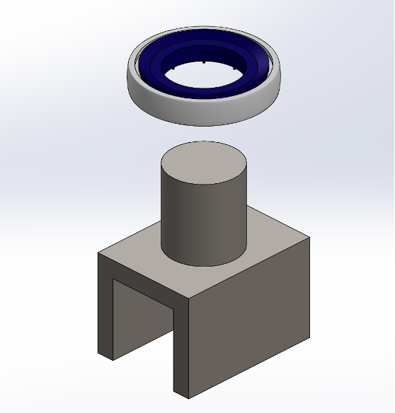
Figure 6a. Exploded view of ride shuttle/wheel assembly.

At the moment the ride vehicle switches from one track to the adjacent track, the top post of the ride shuttle is no longer constrained by the turntable arm and guide rail. To ensure that the ride vehicle makes the track switch, two guide pins are placed in the opening between the tracks as shown in Figure 7. The diameter of the pin must be small enough to fit within the cutout of the ride shuttle but large enough to be effective in guiding the vehicle. Pins with a diameter of 5 inches and a height of 10 inches were chosen to guide the ride vehicle. The pins are designed only to guide the ride vehicle as they will bear no load. Therefore, no stress analysis was used to size the pins. After the ride vehicle passes through the second pin, the top post of the vehicle is caught by a turntable support arm of the other adjacent track moving at the same speed as the turntable of the original track but in the opposite direction. When the top post is caught, it is then constrained against the ride rail of the second track and continues to rotate.
Figure 6b. Ride shuttle/wheel assembly.
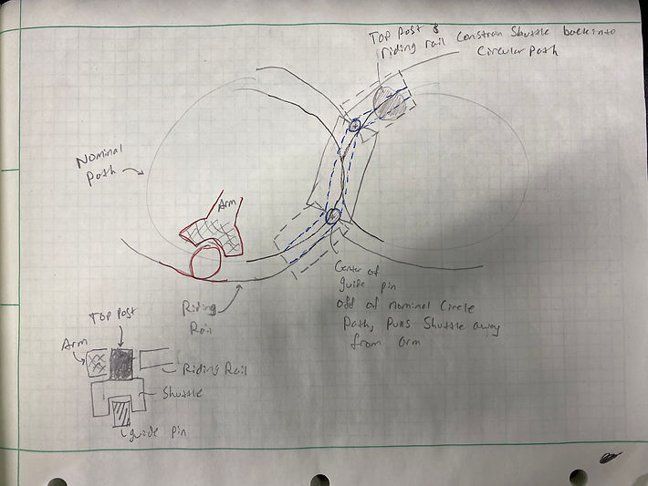
Figure 7. Illustration of ride shuttle being guided by the guide pins through the track switch along a straight path tangent to each ride path.
Design Calculations
The following design calculations are broken down into three sections:
-
Turntable Shaft Sizing
-
Bearing Calculations for Turntable Shaft
-
Ride Shuttle and Top Post Sizing
Click here to see the design calculations
The Finite Element Analysis (FEA) study on the turntable shaft was conducted through SolidWorks Simulation, and the results are presented in Figure 8 and Figure 9. As seen in Figure 8, the simulated value for the von Mises stress was determined to be 1,748 psi. This value aligns closely with the theoretical value of 1,850 psi, obtained from hand-calculations, with a percent error of 5.5%. An axial force, an applied torque, two bearing fixtures, and a fixed geometry fixture were applied to the shaft to model the loading case (see Turntable Shaft Sizing design calculations for free body diagram). Additionally, a fatigue study was conducted using the Goodman criteria, and the simulated value for the number of cycles was determined to be 1x10^11 cycles, as seen in Figure 9. This value is of the same order of magnitude as the theoretical value of 2.19x10^11cycles, found from hand-calculations, with an error of 54%. Thus, infinite life is predicted for the shaft. The results of the FEA study can be deemed to be reasonable and therefore validate the results from the hand-calculations.
FEA Results
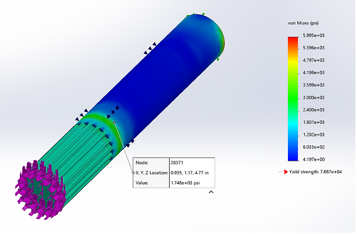
Figure 8. Von Mises stress results from static load study.
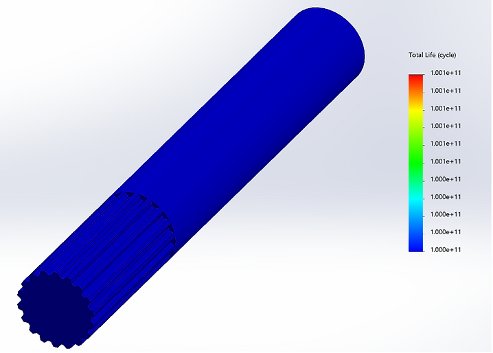
Figure 9. Infinite life cycle prediction using Goodman criteria from fatigue study.
The FEA results for the ride shuttle are presented in Figure 10 and Figure 11. The boundary conditions for this study consisted of an applied vertical load of 166.28 lbf on the top plane of the top post and a fixed geometry constraint between the connection of the bottom of the top post and the rectangular body (see Ride Shuttle and Top Post Sizing design calculations for free body diagram). As shown in Figure 10, the experimental shear stress obtained from the static study conducted in SolidWorks Simulation (6.99 psi) is similar to the theoretical shear stress (7.75 psi) found from the hand-calculations with an experimental error of 9.8%. The stress concentration, with a fatigue stress concentration factor of 2.413, occurs at the interface between the top post and the rectangular feature of the ride shuttle.
Figure 11 presents the results of the fatigue study that was performed on the ride shuttle component. The fatigue study was assigned boundary conditions of the applied AISI 1045 Cold Drawn Steel material, S-N diagram values from carbon steel data, a Kf value of 1, a load ratio of 1, fully reversed load (the bending stress was assumed to be fully reversed) and Goodman analysis setting, and a predicted infinite life. Those boundary conditions produced a study result showing no damage and infinite life predicted all throughout the ride shuttle. This result matches directly with the hand-calculations for fatigue life in which Goodman theory was utilized to predict a factor of safety of approximately 250 and thus infinite life.
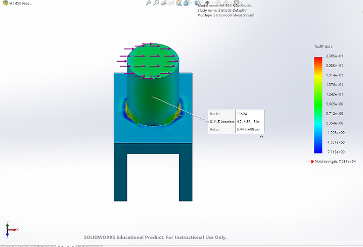
Figure 10. Shear stress results from static load study.

Figure 11. Infinite life cycle prediction using Goodman criteria from fatigue study.
Technical Drawings
Click here to view technical drawings