Davy Jones Animatronic Eye Mechanism

Project Overview
2021
I designed and built this 3D printed eye mechanism as a continuation of my lifelong dream of building a full scale Davy Jones animatronic figure. This mechanism will be paired with the animatronic tentacle beard I previously designed as well as various other mechanisms that will make up the Davy Jones character head.
My goal was to fully design, manufacture, and animate an expressive, emotive, and life-like eye mechanism for Davy Jones.
I will break down this eyeball mechanism by the following sections to help explain how I went about tackling each challenge:
-
Mechanical Design- I designed all of the necessary components for the eye mechanics, the eyelids, and the corresponding four bar linkages to drive the eyeballs/eyelids in SolidWorks.
-
3D Printing/Assembly- I 3D printed all of the parts using PLA plastic and assembled the mechanism with off-the-shelf hardware.
-
Animation- Using Visual Show Automation (VSA), I animated the mechanism side-by-side with a scene of Davy Jones from the Pirates movies.
Mechanical Design
The design constraints for this eye mechanism were as follows:
1) Design each eyeball assembly as a stand-alone, scalable module that can be paired with a mirrored counterpart and integrated into any future character design
2) Design a magnetic attachment for each eyeball shell to magnetically fix to the mechanism
3) Design the mechanism to be compact per the spatial constraints of Davy Jones's head.
Designing the Eye Mechanism
In order for the Davy Jones eye mechanism to be able to emote and be as expressive as possible, it needed to have four basic functions: 1) L/R Eye Up/Down, 2) L/R Eye Left/Right, 3) L/R Upper Eyelid Blink, and 4) L/R Lower Eyelid Blink.
Traditionally, many eye mechanisms simplify the design to include the minimum amount of motors necessary by coupling the left/right eye movements together. This way, a single motor can cause the left and right eyes/eyelids to move up and down or left and right.
However, I wanted to experiment with disconnecting the left and right eye/eyelid movements in order to achieve different expressions in the eyes (see image to the right) as well as to create a standalone module for each eyeball.
I designed the necessary components for the eye mechanics, the eyelids, and the corresponding four bar linkages in SolidWorks while paying careful attention to 3D printing manufacturability, spatial constraints, and proper kinematic design.
The left and right eyeball assemblies are designed to be standalone modules which are mirror images of each other. Each assembly utilizes four motors for the four functions. In addition to enhancing the emotive capabilities in the eyes, the standalone eye mechanism can be easily scaled, printed, and quickly integrated into any character head design. The distance between the eyes can be adjusted with ease as well.
The eyeballs being used in the design were purchased as off-the-shelf components from Amazon and are approximately 24mm in diameter (the minor axis dimension) per regular human eyes. It should be noted the eyeballs are ovular in shape and thus have a major axis (running through the pupil) and a minor axis (running parallel to the pupil).
The range of motion (ROM) for the eyeballs was determined according to the standard ROM for human eyes and are as follows:
L/R Eye Left/Right:
Jointspace: 45° (L) / 45° (R)
Motorspace: 10.25° (CW) / 15.92° (CCW)
L/R Eye Up/Down:
Jointspace: 39° (U) / 38° (D)
Motorspace: 30.35° (CCW) / 28.56° (CW)
All joint types for the various four bar linkages in the assembly were selected based on the necessary degrees of freedom calculated using Gruebler's equation. The four bar linkages driving the L/R Eye Left/Right and L/R Upper/Lower Eyelid Blink functions utilize revolute joints between the crank, coupler, and rocker. The four bar linkages driving the L/R Eye Up/Down functions utilize a spherical joint between the crank and the coupler and a universal joint between the coupler and the rocker. Since the links in this particular mechanism move in three-dimensional space, the joints need to allow for more degrees of freedom so as to avoid unwanted stress/binding and to allow motion to occur. Two spherical joints would also work for this particular four bar linkage.
The eyeball shells were designed to magnetically attach to the mechanism via a high pull, neodymium magnet.
Lastly, the eye mechanism was designed to be compact as the overall dimensions for each standalone eye assembly are 4.7"x 1.9"x 2.6" (LxWxH). These dimensions can be easily scaled down/up and changed to fit the needs of the particular character and spatial constraints.


Example of expression in disconnected eye/eyelid movements.
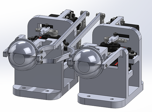
Left and right standalone, mirrored eye assemblies shown in top level design of eye mechanism.
Top level design showcasing the movement of the eyeballs.
Top level design showcasing the movement of the eyelids.

3D Printing/Assembly
Assembly drawing of the top level eye mechanism.
All components for the eye mechanism, excluding hardware and off-the-shelf acrylic eyeballs, were 3D printed using PLA. In addition to being easy to print with, PLA has a low thermal expansion making it a great choice for printing very large and very small parts (the parts do not warp on the heatbed). Additionally, PLA parts are very hard. Due to the nature of the small parts in the eye mechanism moving at high speeds with relatively tight tolerances in a compact space, the PLA parts were hard enough to avoid any problematic flexure while still fitting together easily during assembly.
Huge shoutout to Michael Wadsworth with Nova Engineering, LLC for printing these parts for me! The turnaround time was excellent and very quick at a low price for high quality prints! Thank you a ton, Michael! I will also mention that Michael is an excellent mentor, fantastic engineer, and all around amazing person. Go check out his LinkedIn profile!
The parts were printed on an Ender CR-10S4 printer using a 0.8mm extruder and standard printer settings.
Assembly and build photos are shown below.


Animation
The eye mechanism was controlled using an SSC32U servo controller board by Lynxmotion and was animated using Visual Show Automation (VSA) by Brookshire Software. Check out some of the incredible key features of this powerful and robust animation software. Among the most impressive is that it can support up to 128 tracks (servos, motors, relays, and dimmers).
The SSC32U servo controller can support up to 32 servos at once and provides a variety of power options and additional functionality for almost any use case out there. All servos being used for this mechanism are Hitec HS-81 micro servos being powered with a 6V power supply. The power supply is connected to the VS1 rail of the SSC32U via a wiring harness and is sufficient for powering both the servos and the logic of the board. This project could be integrated with many more servos and various other mechanisms as there are 32 total PWM connections on the SSC32U. If a project required servos that run on different voltages, this board could handle that because the VS2 power rail can be powered separately with its own power supply via the VS2 power terminal on the SSC32U.
For more information on the functionality and capabilities of the SSC32U, check out the manual.

SSC32U setup showing servo and power connections.
Initial calisthenics for the eyeballs prior to attaching the eyelids.
Eye roll test for the eyeballs prior to attaching the eyelids.
Eye mechanism in action side-by-side with VSA animation window.
Davy Jones eye mechanism in action side-by-side with the movies.
In the Future
Stay tuned...
Moving forward, I plan on continuing to prototype different mechanisms for the Davy Jones character head, different mechanisms for the full body, and also some shell designs for the figure. Stay tuned as I continue to develop this project and strive for a lifelong dream of mine to design and build a full-sized animatronic Davy Jones figure!